Michael J's build #2

Re: Michael J's build #2
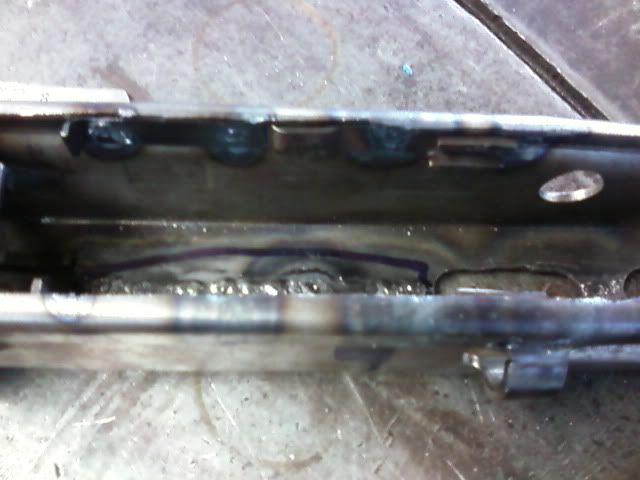
Yes,sorry Michael.but it is totally ruined,cannot be fixed.You should put it in a box and send it to me,I will put it where others will not see it and make fun of Canadians.Well,not more than usual.Though you guys did kick a$$ in that South Park documentary!  Look at your rails-you will see the raised flat section,that protrudes through the receiver through the D hole,the flat part determines how far forward or backward the rail goes,also the hole controls up and down for the front of the rails.Two points in a line,if you move one,it changes the angle comparative to the center line of the receiver.There is a print here somewhere.Check it out,and the hole can be contoured with some welding and filing.When did you start drilling holes anywhere?Are there fumes in the shop?
 Not to worry,it is easy compared to what you have gotten done already! ---bil
"I dream of a world where I can buy alcohol,tobacco and firearms from the same drive-up window,and use them all on the way home from work!" Dogbert
-
Michael J
Re: Michael J's build #2
Oh i see! I did not intend for the D-holes to be used for aligning my rails. I placed my rails inside of the receiver first, then determined where they should protrude, marked that out with a sharpie, and cut away enough so that they may protrude out of the D-hole adequately.
However, while we are talking about rail installation... To align my rails, i aligned them to the cam, and had planned to insert my barrel, lock in the bolt and use that to keep it in place (i'm going to weld my rails in). I also have a piece of wood i will be using to keep the rails parallel with each other so that i can weld them in place properly.
But i think to make life easier, i will just have to pack er up and send it to Bil to be disposed of properly ! I have seen us canadians on south park, very accurate portrayal , yes
  !
!
However, while we are talking about rail installation... To align my rails, i aligned them to the cam, and had planned to insert my barrel, lock in the bolt and use that to keep it in place (i'm going to weld my rails in). I also have a piece of wood i will be using to keep the rails parallel with each other so that i can weld them in place properly.
But i think to make life easier, i will just have to pack er up and send it to Bil to be disposed of properly
-
flemgunner

- Brigadegeneral

- Posts: 635
- Joined: Sat Apr 21, 2007 6:35 am
- Location: Texas
- Contact:
Re: Michael J's build #2
Install the recuperator before you install the rails it will make alignment much easier
-
Michael J
Re: Michael J's build #2
Oh yes, i forgot to mention that , it was put into my receiver before i fiddled around with the rails ! Thank you though for the reminder, i'm sure i could have easily made that mistake. I seem to do dumb things in that shop ... i am blaming it on the argon i am exposed to , yup  ! Like the time i welded my barrel shroud on upside down with the barrel door to the left ...
-
Michael J
Re: Michael J's build #2
Rails welded in place, both align up perfectly to trunnion and barrel too. Bolt slides back and forth absolutely flawlessly . I will test my charging handle and what not in a few days. Awful busy with my final exams for this semester... 
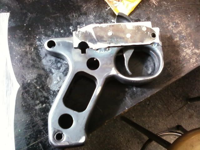
Got my FAL grip all made up, holy crap installing the sear into the trigger with that darned spring is a challenge all by itself ! Umm, and the pins supplied by Pirate for my hammer were like 1/8 too short, so they wouldn't even't even sit i my FCG box . Haha ah well, i pilfered this 5mm drill bit and cut it to size . Oh man is that hammer spring a tough guy to depress! I had mocked up the parts, go to cock the hammer back, slipped and that hammer spring was like a mini rocket!
Also it seems i tacked my trigger plunger too far back! Now that the FCG box is fully welded onto my grip, fixing this becomes a bit of a task :/... The cons of buying the trigger parts AFTER assembling your box, so i strongly suggest that anyone who plans on doing your build with this grip, to mock up the trigger first! I will remove the plunger, weld on an extension, and trim it to the correct diameter on the lathe i guess. Should be a joy! By the way, metric C1 / L1A1 parts.
To-Do list:
-Buy bolt conversion parts
-Get my required parts handled, if plan A does not pull through, I can always fall back onto plan B if the offer is still up . Plan A, still need to know if it's a go or if i should fall to plan B !
- TEST FIRE
Got my FAL grip all made up, holy crap installing the sear into the trigger with that darned spring is a challenge all by itself
Also it seems i tacked my trigger plunger too far back! Now that the FCG box is fully welded onto my grip, fixing this becomes a bit of a task :/... The cons of buying the trigger parts AFTER assembling your box, so i strongly suggest that anyone who plans on doing your build with this grip, to mock up the trigger first! I will remove the plunger, weld on an extension, and trim it to the correct diameter on the lathe i guess. Should be a joy! By the way, metric C1 / L1A1 parts.
To-Do list:
-Buy bolt conversion parts
-Get my required parts handled, if plan A does not pull through, I can always fall back onto plan B if the offer is still up
- TEST FIRE
-
Michael J
Re: Michael J's build #2
Update on my to-do list.
1) Buy bolt mods
2) Apparently trim my plastic grips to fit the new grip stick (forgot about this one )
3) Install missing parts that i had needed
4) Do final fitting/adjusting
5) Test fire!
I will get some pictures up sooner or later. I also think i will need to re-enforce the welds holding my rails, as they are only tacks, and would probably come loose after a few shots!
I am nervous about my grip and bolt... I suspect that because my gripstick is slightly bent towards the right (the way it sits, i'll get pics of it), that the hammer may not correctly align up to the firing pin .
I will fiddle with that when i get down to the final fitting stage, but i've a bad feeling...
1) Buy bolt mods
2) Apparently trim my plastic grips to fit the new grip stick (forgot about this one
3) Install missing parts that i had needed
4) Do final fitting/adjusting
5) Test fire!
I will get some pictures up sooner or later. I also think i will need to re-enforce the welds holding my rails, as they are only tacks, and would probably come loose after a few shots!
I am nervous about my grip and bolt... I suspect that because my gripstick is slightly bent towards the right (the way it sits, i'll get pics of it), that the hammer may not correctly align up to the firing pin
I will fiddle with that when i get down to the final fitting stage, but i've a bad feeling...
-
Michael J
Re: Michael J's build #2
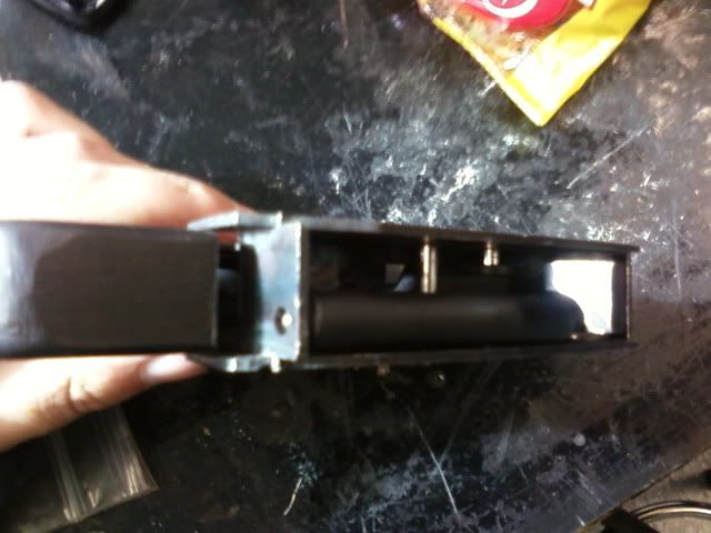
All major components installed onto receiver ! I still must install front and rear sights, tripod lug, and rivet on the little thingy underneath the buffer that keeps it from twisting.
Used a spot welder to install the barrel door supports that i salvaged from cut pieces off of an old shroud (special thanks , you know who you are ). Installed the barrel guide thing and riveted on the barrel door. It currently isn't shutting properly (locking in), i suppose due to the angle which the door sits on, so i will fill the door locking piece until it slides back and forth smoothly!
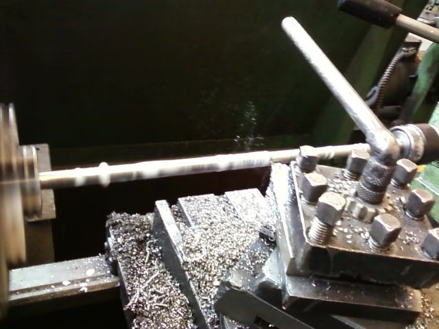
Well I opted to build my bolt parts myself! It took me a class to lathe the rear, but saved me like $40. Here is a picture of it in its rough form, and below is are nicely sanded up-close pictures of it.
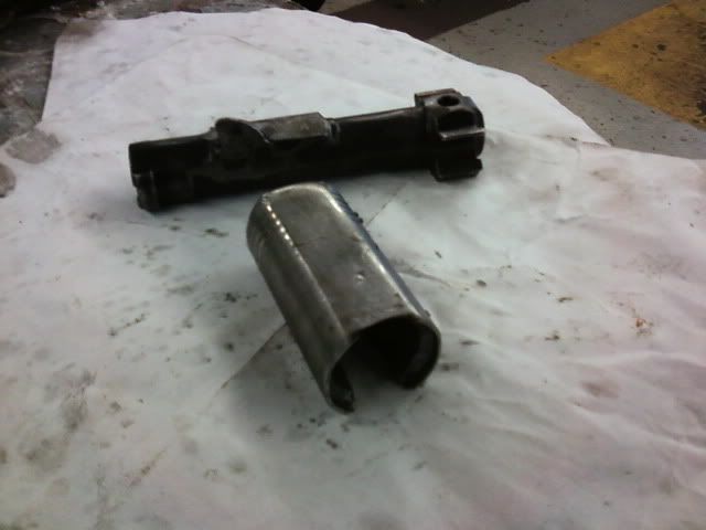
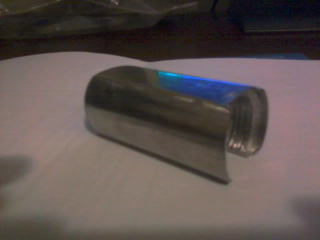
Gosh, now that I've the hang of it, I should make more to sell LOL ...
Anyways, i will start work on the firing pin sooner or later, and umm, I'm pretty much done! Just have to work out the bugs in everything and at least it will be functional (hopefully ). After it is all approved and whatnot, I will throw on the sights plus AA mount, and tripod lug. Holy cow, this has taken me a LONG time to do...
Used a spot welder to install the barrel door supports that i salvaged from cut pieces off of an old shroud (special thanks , you know who you are
Well I opted to build my bolt parts myself! It took me a class to lathe the rear, but saved me like $40
Gosh, now that I've the hang of it, I should make more to sell LOL
Anyways, i will start work on the firing pin sooner or later, and umm, I'm pretty much done! Just have to work out the bugs in everything and at least it will be functional (hopefully
-
42rocker
- Administrator

- Posts: 3325
- Joined: Fri Jan 11, 2008 6:03 pm
- Anti-spam: Mg42
- Location: Florida
Re: Michael J's build #2
1st GOT grease???? LOL
2nd NICE lathe work.. Maybe you should start to sell a few extra's. Pratice by making yourself 6 or more then start to sell a few extra's.....
3rd WAY TO GO.... All major parts installed!!!!!!
GOOD LUCK with the paper work!!!
Again WAY TO GO!!!!!
Later 42rocker
2nd NICE lathe work.. Maybe you should start to sell a few extra's. Pratice by making yourself 6 or more then start to sell a few extra's.....
3rd WAY TO GO.... All major parts installed!!!!!!
GOOD LUCK with the paper work!!!
Again WAY TO GO!!!!!
Later 42rocker
-
Michael J
Re: Michael J's build #2
Thanks 42rock (got WAY to much grease ) , well my gripstick is officially working and ready to go as of today! Had to lengthen my trigger return spring, it was like a 1/8" too short! Just welded some material to it, and ground it to fit (very tedious to install and remove...). All thats left is to sandblast it, and then finish it, but I will do all my cosmetic work after my gun is functional!
Took me 4 and a half hours, and a foot of drill rod to make this damned firing pin thing... I started with some 3/16" stuff i think, way to flimsy to just cut. I'm sure i was doing something wrong, had my carbide bit nicely sharpened, and was running at 200rpms. Normally that would cut through anything perfectly with auto-feed on, but it kept flexing the drill rod and bending it! So i stepped it up to some 3/8" stuff, and slowly (and evenly) removed metal , flipping it back and forth. Way too much work for the silly firing pin, what the heck was I doing wrong ???
Will weld some parts onto the firing pin, and weld the original pin to the end. Thank you Lima for your information you gave me!
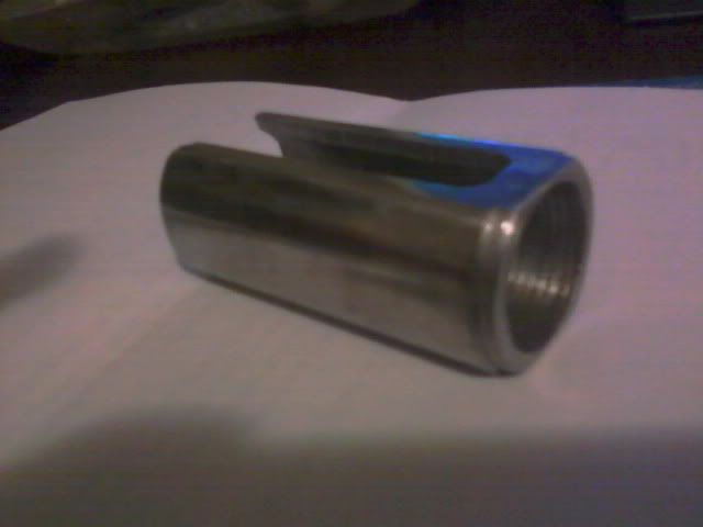
As for the bolt extensions, the inside of mine looks like crap! Dull drill bit , i will ream any future ones if i make a couple to help fund my projects. The inner and outer dimensions on Thompsonmachine.net are a bit off from what I found... Just a heads up to anyone planning on using the tutorial. Perhaps just because of my yugo bolt carrier?
Took me 4 and a half hours, and a foot of drill rod to make this damned firing pin thing... I started with some 3/16" stuff i think, way to flimsy to just cut. I'm sure i was doing something wrong, had my carbide bit nicely sharpened, and was running at 200rpms. Normally that would cut through anything perfectly with auto-feed on, but it kept flexing the drill rod and bending it! So i stepped it up to some 3/8" stuff, and slowly (and evenly) removed metal , flipping it back and forth. Way too much work for the silly firing pin, what the heck was I doing wrong
Will weld some parts onto the firing pin, and weld the original pin to the end. Thank you Lima for your information you gave me!
As for the bolt extensions, the inside of mine looks like crap! Dull drill bit
Can't quite remember, but i do believe the 2nd 1.280" should be smaller, to fit properly.I start by turning a 1.5" steel bar to 1.280" diameter
for a distance of 2.6" and drill a 13/16" hole 2.5" deep
...
Then its time to cut the angle on the inside edge that
matches the projection on the rear of the stock carrier.
I have found its easiest to just
set the compound slide to just under 6 degrees and
use the boring bar, checking the fit
after every pass. You will also need to turn the outside
diam of the first .10" to a diameter of 1.280 to
fit inside the spring ret ears on the original
carrier.
-
42rocker
- Administrator
- Posts: 3325
- Joined: Fri Jan 11, 2008 6:03 pm
- Anti-spam: Mg42
- Location: Florida
Re: Michael J's build #2
Ok, have not done a lot of lathe work but can't you use a support using 3 brass pieces in the middle then cut one side then move support then cut other side. That might show that I have not done a lot of lather work.... Also someone that knows a lot more than myself might want to double check the angles of your cutting tool bit. (might be perfect but?)
I'll be happy when I get to where your at Michael... Keep up the Good Work..
Later 42rocker
I'll be happy when I get to where your at Michael... Keep up the Good Work..
Later 42rocker
-
Michael J
Re: Michael J's build #2
Yes, i think there are supports that can be used, but i don't have anything like that at the shop42rock wrote:Ok, have not done a lot of lathe work but can't you use a support using 3 brass pieces in the middle then cut one side then move support then cut other side. That might show that I have not done a lot of lather work.... Also someone that knows a lot more than myself might want to double check the angles of your cutting tool bit. (might be perfect but?)
I'll be happy when I get to where your at Michael... Keep up the Good Work..
Later 42rocker
-
42rocker
- Administrator
- Posts: 3325
- Joined: Fri Jan 11, 2008 6:03 pm
- Anti-spam: Mg42
- Location: Florida
Re: Michael J's build #2
Michael
try this website
www.sherline.com
Of course their stuff can only use their stuff.. That said.. They have a lot of basic machineing stuff on that website with links to other websites that can help also..
The part that I was tring to talk about for doing support work is the following
http://www.sherline.com/1090pg.htm
which with a "little" work can be made.?.?.?
"""The purpose of the follower rest is to keep long or small diameter work from deflecting when a cutting tool is applied to it. It is attached to the lathe saddle and moves as the saddle moves, keeping the point of support directly behind the cutting tool. This helps you maintain accuracy on long cuts and on small diameter stock.
READ INSTRUCTIONS FOR USING A FOLLOWER REST (Click on your choice.)
.html Version (Web site version) """"" from the above site..
Also if your using something like the above use lots of oil NOT grease... LOL .... really use lots of oil on the brass supports..
Keep up the good work HOPE to catch up to you some day..
Later 42rocker
-
Michael J
Re: Michael J's build #2
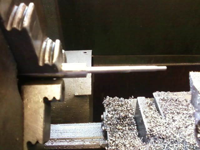
Well i figured out the solution to my problem today, redesigned and made a new firing pin, heat treated it, then made a support insert.
First of all, what I did was left the original OD of like 3/8 in the chuck , and turned it down to firing pin diameter half an inch at a time. each time stopping the lathe, and advancing the rod.
My firing pin fits perfect, and is quite similar to the BRP one dimension wise, although my spring-stop sits 1/16" farther back than BRP due to a calculation error ... Didn't make a difference though . Found this spring, appears to have an OD of 1/4" . Might have to cut it a bit down, and it is also tough as heck, i hope its not too stiff... WAY better than the one i attempted to make
Finally, made a support bushing by cutting down some copper round stock, and pressing them together, in the vice. Also drilled the other thing for the firing pin to go through. Mocked it all up, no binding or anything, all is good!
All thats left is to make that pin thing that holds the ejector-assist-pusher in, on the rear. Don't quite know how i'll drill it, but i'll figure it out .Then I must weld on my bolt extension, then done the bolt!
After this bolt, I just gotta work out the bugs on my gun, and should be ready for test fire!
First of all, what I did was left the original OD of like 3/8 in the chuck , and turned it down to firing pin diameter half an inch at a time. each time stopping the lathe, and advancing the rod.
My firing pin fits perfect, and is quite similar to the BRP one dimension wise, although my spring-stop sits 1/16" farther back than BRP due to a calculation error
Finally, made a support bushing by cutting down some copper round stock, and pressing them together, in the vice. Also drilled the other thing for the firing pin to go through. Mocked it all up, no binding or anything, all is good
All thats left is to make that pin thing that holds the ejector-assist-pusher in, on the rear. Don't quite know how i'll drill it, but i'll figure it out
After this bolt, I just gotta work out the bugs on my gun, and should be ready for test fire!
Re: Michael J's build #2
Looks great! I wonder if a spring from a pen would work? Of course,the pen wouldn't be any good any more,so try it with someone elses pen! Also you might want to look over on Weapons Guild,there is a whole section there with tips and links for machining almost anything,excellant stuff! Keep up the good work! ---bil
"I dream of a world where I can buy alcohol,tobacco and firearms from the same drive-up window,and use them all on the way home from work!" Dogbert
-
Michael J
Re: Michael J's build #2
Thanks for that link 42rocker, hmm, i could make something like that! I'll have to think up a way of attaching it to the lathe, i'll start making some drawings...
Bil, i tore apar 3 pens (broke, they didnt untwist, i untwisted like 5 ), and one lead pencil, and they are too small, I blame you!!!!!
Perhaps I will just trim the current spring so there is less tension and shorter travel.
I'll keep updating this thread, and thank you everyone for the help and support
Bil, i tore apar 3 pens (broke, they didnt untwist, i untwisted like 5
Perhaps I will just trim the current spring so there is less tension and shorter travel.
I'll keep updating this thread, and thank you everyone for the help and support
-
DougF
Re: Michael J's build #2
I think that trimming the spring will actually increase the tension. You might consider heating it instead. The bolt extension looks good Michael. The surface finish of the inside won't matter because there is nothing rubbing against it. Keep up the good work.
-
Michael J
Re: Michael J's build #2
I figured less distance per same force would be less work. My bad for using the term "tension", I could not think up the correct word at the time. Reducing the length will increase tension lol, but i think tension is mostly referred to measure a "pulling apart force". Less than useful for the FP spring, which is being compressedDougF wrote:I think that trimming the spring will actually increase the tension. You might consider heating it instead. The bolt extension looks good Michael. The surface finish of the inside won't matter because there is nothing rubbing against it. Keep up the good work.
I'll give heating it a try after, as i need to shorten the spring anyways for fit purposes. I'll let you guys know how it all works out!
-
Michael J
Re: Michael J's build #2
Done welding the bolt!
Now that i've sort of thrown it all together, i have a LOT of fitting problems ... Individual parts fit, but once you throw em all in there, it is one big bind-fest  .
.
I need to file the right rail, trim the charging handle to clear the hammer, and the top of it to clear the bolt, file the U-bracket as it is binding with the barrel door, trim my welds there as the door won't fully close with the barrel in, cut my main spring, and adjust that charging handle lug on the bolt by pulling it closer to the edge. After that, I will see how it is running, those are the only things wrong that I can think of .
Hammer clears bolt extension perfectly, i was really worried at first about that one, glad that it works! I trimmed the firing pin spring to fit better, i am still not sure if that spring is too strong or not, but I won't find that out until i test-fire, and see if i get weak primer hits.
Holy cow, I thought getting the receiver and all that built was tough, that was only half the battle! I have also got to say, building this from the raw stampings was much harder than anticipated, I hope to use a pre-welded shroud next time, as doing it myself has caused some problems for the build...
I'll update as i work out the bugs.
Michael
Now that i've sort of thrown it all together, i have a LOT of fitting problems
I need to file the right rail, trim the charging handle to clear the hammer, and the top of it to clear the bolt, file the U-bracket as it is binding with the barrel door, trim my welds there as the door won't fully close with the barrel in, cut my main spring, and adjust that charging handle lug on the bolt by pulling it closer to the edge. After that, I will see how it is running, those are the only things wrong that I can think of
Hammer clears bolt extension perfectly, i was really worried at first about that one, glad that it works! I trimmed the firing pin spring to fit better, i am still not sure if that spring is too strong or not, but I won't find that out until i test-fire, and see if i get weak primer hits.
Holy cow, I thought getting the receiver and all that built was tough, that was only half the battle! I have also got to say, building this from the raw stampings was much harder than anticipated, I hope to use a pre-welded shroud next time, as doing it myself has caused some problems for the build...
I'll update as i work out the bugs.
Michael
-
Michael J
Re: Michael J's build #2
quick update, fixed all the minor bugs, just have to reweld the tab on my bolt carrier that the charging handle hooks onto. It needs to be further towards the side, so i'll just fix that. I will then run the action and make sure it is all smooth, probably (but hopefully not), make up a new list of things to fix ...
After i get it running smoothly, i'll try running it dry with some ammo at a range. If it feeds and all that good, I will test fire. I'm thinking my hammer spring might be too strong, so i might have to replace that , but easily done. Also might have to trim my recoil spring, as it is at about 7 coils removed (pirates tutorial says 8 ), so iwill fine tune that too.
Once it functions, i will submit it for approval, (if returned) install the sights and tripod mounting lug. Give her a nice presentable finish, and have some fun!
-
www.Prussia.us

- General

- Posts: 1060
- Joined: Sun Jan 06, 2008 7:17 pm
Re: Michael J's build #2
Good Show Michael, yes the final fit on these rebuilt parts kits can nearly drive one mad
“… corporations have been enthroned, and an era of corruption in high places will follow, … until all wealth is aggregated in a few hands and the Republic is destroyed.”
- Abraham Lincoln (Republican), Nov. 21, 1864
- Abraham Lincoln (Republican), Nov. 21, 1864