Gungrubbers semi bolt design how to

Ask your build questions here. Welding, assembly, etc.
Post Reply
Gungrubber

Gungrubbers semi bolt design how to

Post by Gungrubber »

tools and material list

Heres what tools I have and used to make this conversion.
7x10 mini lathe with a selection of bits (I got the indexable carbide ones)
a tool steel blank bit to grind or a very small boring bar (this is to bore the wedge collar)
another blank to make a very small threading tool for the roller assembly threading
an 8x36 tap
harbor freight micro mill with a vise and milling bits (this was to machine the flat on the wedge collar/firing pin support tube) you could probably do this with a belt sander or a file
or a grinder if your careful all the flat is there for is so the ejector will clear the support assembly
a 3/16 Carbide tipped drill bit (to drill the locking wedge) carbide is a must!! anything else won't even scratch it.
A torch capable of heating steel to bright red (for hardening the pin and roller) a good hot fire would work too.

Material list

6 in section of 3/4 round steel (main support assembly)
6 in section of 1/2 round steel (rear assembly, roller assembly, lugs ect.)
at least 6 in of 5/16 round steel (firing pin)
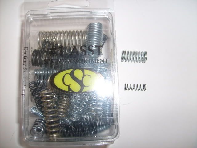
springs (I just picked up the no 1 spring assortment by csc at tractor supply)
a can of kasenit case hardening compound (for the roller and firing pin)

ok starting with the main forward section
Image

This uses the 3/4 steel

chuck the section of 3/4 steel into your lathe you will need at least 3 3/4 in working area
beyond the chuck (the finished section will measure 3.359 in when completed) first true the face of the piece then turn the entire length (3 3/4 in) to a diameter of .616 this gives you the outer diameter for the wedge collar (you may need to go a bit smaller depending on your bolt dimensions. test fit and make sure it fit's in the bolt body easily)

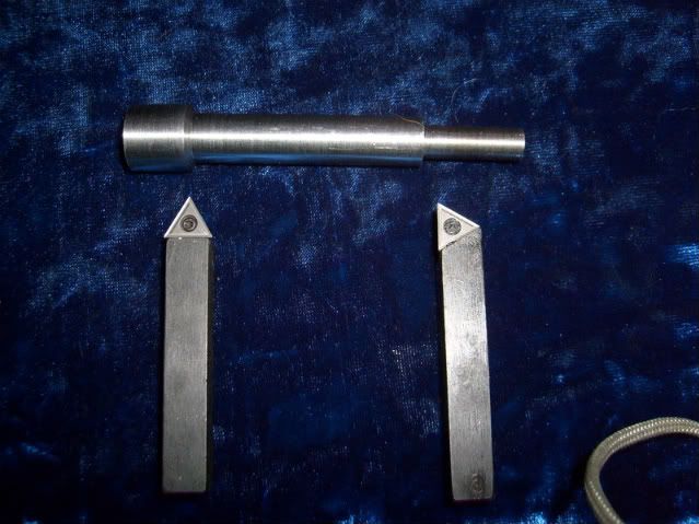
Next turn a distance of 2.955 in from the end of the piece to a diameter of .452 (I used the straight point turning tool to do this (the left hand tool bit in the pic) this turns the 30 degree shoulder at the same time as your turning to the correct diameter) the length measurement is from the end to the start of the 30 degree shoulder if using the tool like I did stop the point right on 2.955 in and you will have it right .

Next Switch to a 90 degree turning tool (right one in the pic) and turn from the end .916 inches to a diameter of .302 in this is where the tension spring will ride

at this point you should have something similar to the pic in outer dimensions

now you will need to part it from the parent steel. leave a bit extra on the part so you can true the face of the piece down to the correct length of 3.359 in

Next starting at the wedge collar end (I am assuming this is the end that is facing out because you have just trued it) use a center drill to start the hole and drill a 3/16 in hole the entire length of the piece (this will be the firing pin channel)

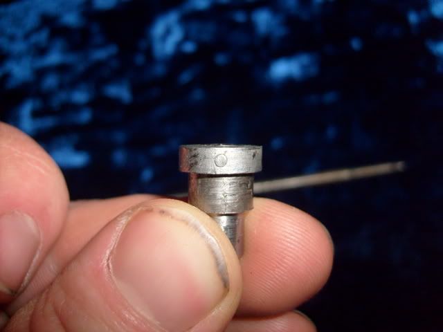
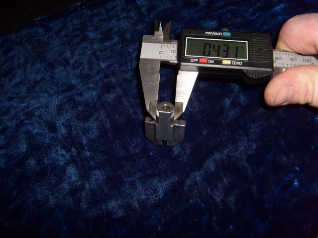
Now for the tricky part ! The wedge collar. Pull out you calipers and measure the outer diameter of your locking wedge where it will go into the collar.
Image

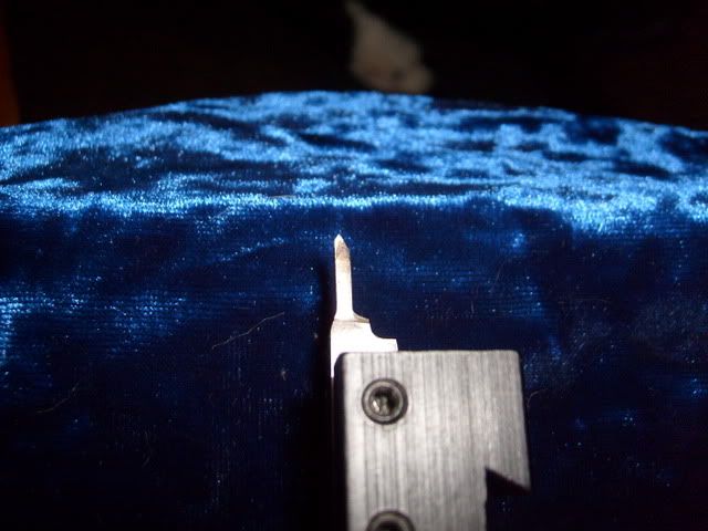
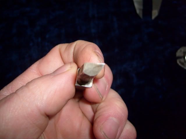
Mine measures .431 as you can see. as there are most likely variations on sizes within a few thou you gotta know what yours measures. now use a drill to get as close as possible to the correct size without going over. the depth needed on my wedge is .472 in a little deeper is ok because the wedge will seat against the rim of the collar. Drill to the correct depth to get as close to size as possible then using a small boring bar or a boring tool like this one I made (my bar is an indexable and was too big) to bore the collar.
Image
Image
Image

bore the collar to the correct inside diameter add a thousandth or 2 for clearance
(bore a thou. Clean the chips and try the wedge for fit. then repeat untill it fits make sure your cuts are good and to full depth the collar needs to hold the wedge straight for the firing pin to work right) DON'T RUSH!!!! I got in a hurry and had to remake the whole part
because I didn't get the cut straight and the wedge fit too sloppy. take your time and get it right. touch a file to the outer edge to clean it up. collar done.

now the last lathe operation on this part. turn the part over so that the small diameter section is now facing out. now drill with a 5/64 drill bit to a depth of .320 this gives you your firing pin spring seat.

So at his point you have your part outer turning finished, wedge collar bored to size and finished, firing pin channel and spring seat drilled and finished. The part should be at the finished length of 3.359 in.

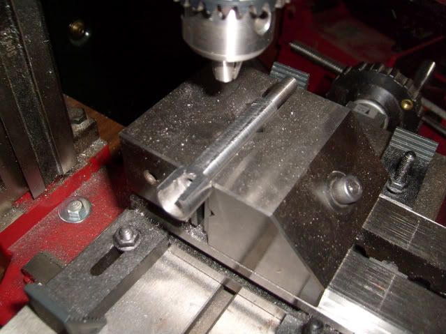
now it's over to the mill to mill the flat. I stuck it in my milling vise on a pair of parallels
so roughly 1/2 it's diameter is above the vise face and the vise grips on the longer center section like so.
Image

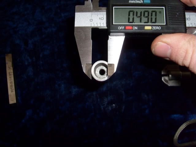
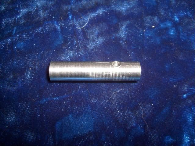
mill it down (making sure your straight of course) so that from top of the collar to the mill flat measures .490 or less.
Image

that completes this section.

Gotta take a break guys more to come.
GG
Gungrubber

Re: Gungrubbers semi bolt design how to

Post by Gungrubber »

Next part

Rear assembly center section
Image

this uses 1/2 in steel

chuck your section of 1/2 in steel into the lathe true the end and turn 2 in of it to a diameter of .389 in. center drill and then drill a 3/16 hole 2 in deep through the piece.
switch your drill to a letter N size (this is an oddball you might have to order it) or use a 19/64 ths and offset it a bit. now drill with your bit to a depth of .888 in and make sure it slides together with the front section part section off and true end to a finished length of 1.709 in touch the sharp edges with a file. ... lathe work done

Mill work

set your section up in the vise on the mill so you can drill through it for the roller attachment threads (the hole you see in the pic) set to drill .460 in in from the end with the 3/16 hole (the back of the assembly) carefully center drill the exact top center of the
part at .460 from the back end. (this is critical because we will be drilling all the way through doing the top and bottom roller attachment holes at once) once you are sure of exact top center and have your starting point center drilled use a #29 drill to drill both holes then tap the holes using an 8 36 tap. clean all the burrs off from tapping and drilling
and we have finished the rear section.

more to come tomorrow guys.
Gungrubber

Re: Gungrubbers semi bolt design how to

Post by Gungrubber »

Sorry for the delay guys. power was off here yesterday. :?

ok final 2 pieces for the bolt conversion roller studs and firing pin.

Image

(there is also the rear extension piece but I just used pcbb's excellent how to on that
so there is no need to repeat it here just check out his how to or buy one pre made from him.)

ok rollers first this uses 1/2 steel for the top and you can use a smaller diameter for the bottom as it is only a threaded stud.

Bottom stud is the simple one ( using smaller diameter steel helps shorten the turn down quite a bit) turn a section about 1/2 inch long to a diameter of .275 in then turn exactly
.100 from the end down to .167 in diameter now set it aside we will turn the upper part before setting up the lathe for threading.

Upper roller is 2 pieces the stud and the roller.

turn a piece of 1/2 in steel to a diameter of .375 in for a length of .900 in
then turn the first .100 in to .167 in for the thread turn the next .276 in to a diameter of .276 in

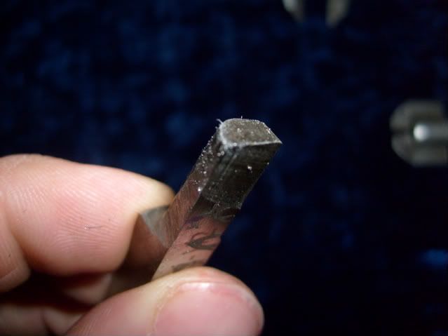
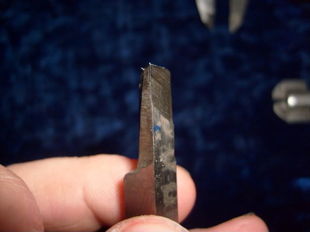
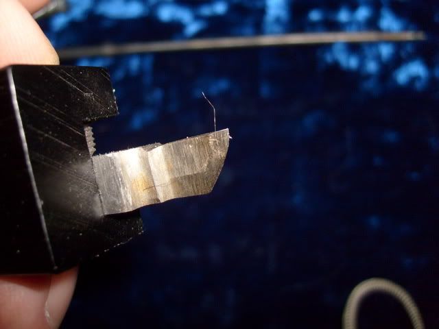
Now set up to thread I had to make a special small threading tool

Image
Image


it's a very narrow ground tool blank with a 60 degree threading end on it

(you might be able to do these with the correct type of threading die but I used the lathe)
I set up for threading 8 36 and set the lathe so it was JUST turning and very carefully threaded the .167 studs on both the roller blanks. we want the threads to fit tight
so they will not come loose after assembly (I will use loctite when doing final assembly just to make sure)

ok now part off the 2 roller stud sections and true to the following finished lengths

Top .760 in
Bottom .382 in

now take a section of 1/2 in steel true the end and turn a section about .400 in long to a diameter of .470 in. Center and drill a hole the same depth with a 17/64 drill then CAREFULLY part off a section EXACTLY .140 in long This will be your roller measure the inside diameter with a caliper for the next step

now take that top section and chuck it back into the lathe with the threaded end facing in
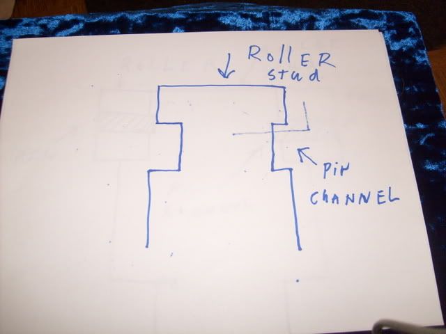
turn the first .140 in to a thousandth or so under the measurement you got above for the roller id then cut the pin channel into the roller post this requires a tool very similar to the threading tool but with a flat end not a point I just bought some brad nails for the pins and hardened them when I did the roller and the firing pin.

once you cut the pin channel (it's up to you how deep you want to cut it try to keep it shallow to keep the roller post strong) set the top aside

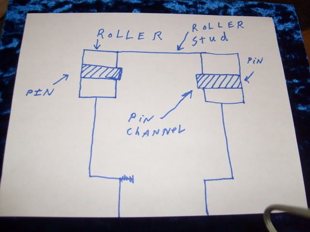
Some badly drawn cutaways of the roller assembly top to show exactly how it goes together and clarify how I made it
Image
Image

as you can see you will need 2 holes drilled in the roller for the pins I just set it up like I did the rear section to drill the roller stud holes and drilled them both at one time.
match up a drill bit to your pins (these are drive in pins so we want it a thou or so on the small side compared to the pins) and set up and drill the holes on the mill.

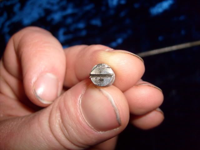
you need to now slot the bottom roller for a screwdriver I just used my dremel and a cut off disc.
Image

on to the firing pin

you need the 5/16 steel for this

I turned it in short sections because of the small diameter necessary for the pin and the flex in the steel the Critical dimension on this is from the tip of the pin to the stop collar
must be exactly 5.300 in for the first section I turned (the front of the pin ) I used the
original pin as a guide and copied it's dimensions to get the gradual sloping shoulders on the pin I simply used a file to shape them while the lathe was running (it's easy)
I turned the pin in sections back to the stop collar to a diameter of .175 this gave me a bit of clearance for any minor misalignment or flex. then I turned the stop collar it is .100 in in length and .282 in in diameter. Now I made my pin a lot longer than needed on the rear end so I can trim it to perfect length for my fcg setup. You won't need any where near this length but I felt it better to go long while I was turning so I would have plenty to spare the 3 inches of pin at the back behind the collar are turned to.180 in diameter in
sections just like I turned the first part. I polished it a bit with some emery paper then we part the finished pin off.

now we have to harden the firing pin the roller and the pins I used Kasenit hardening compound you heat the parts to a bright red with a torch. Dip the in the compound that forms a kind of shell around the part heat them to bright red again and immediately quench in water. (warning when you do this it makes a crack!!!! noise don't be alarmed it's supposed to also make sure you have the firing pin straight up and down when you quench it so it doesn't warp) harden the firing pin, Roller, and roller pins. Clean off the residue from the kasenit and the parts should look kinda dull grey.

(NOTE) you could turn the roller and firing pin from tool steel and skip the hardening if you know how to turn tool steel.

now put your roller on the roller stud drive in your pins and grind or file em off flush with the roller like this.
Image

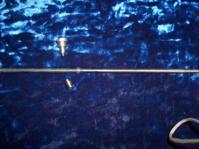
Now assemble using your chosen springs from the spring pack. Heres the one I got
And the springs I used.
Image

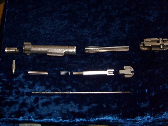
grinding the lugs and fitting the extension piece is detailed elsewhere on the site so I won't rehash it here. I'll just keep it to the changes and elements I designed.

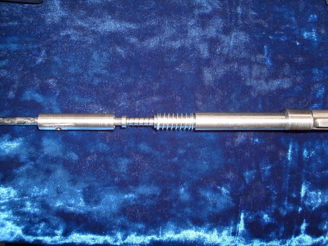
There will be some fit and try involved I tried each part for fit as it was made as much as possible to make sure things went together properly. like this
Image
Image


This was written with the assumption that the one making it will know basic lathe operations and mill operation because you will need to know this to build the conversion
(you or whoever you can sweet talk into doing it for you :mrgreen: )

Well Fellas What do you all think of this Frankenstein project of mine?

Need anything explained better? post and I will try to clear it up.


GG
hcpookie
Hauptmann
Hauptmann
Posts: 125
Joined: Sun Jun 12, 2005 10:42 am
Contact:

Re: Gungrubbers semi bolt design how to

Post by hcpookie »

I think it looks great! Range reports and pictures of fired primers would be nice. :)
hcpookie
Hauptmann
Hauptmann
Posts: 125
Joined: Sun Jun 12, 2005 10:42 am
Contact:

Re: Gungrubbers semi bolt design how to

Post by hcpookie »

A few thoughts.

Would a more permanent fit between the main body and the locking wedge work better? As in using a press fit to attach the collar onto the locking wedge? You could use a bearing press to press it into place, then mill the flat on top.

Another idea is you could blind pin it into place? I'm not sure if I'd want to weld the locking wedge because of the heat it would impart, probably altering the temper of the steel.


QUESTION: The ID of the firing pin housing would need to be slightly larger than 5/16", correct? Here's a thought - I found at the OnlineMetals website they have a 4130 tube with OD .75" and ID .375" (3/8"). that's 1/16" larger than the firing pin.

Now, could you take that tubing and make a firing pin with a bearing surface (I use that term loosely) that is larger than 5/16" to let the main body of the firing pin "float" in the housing? Less surface area of the firing pin that is in contact with the housing would result in less friction, and easier ignition. Also, it would be a more robust design since it would be less sensitive to dust/grime/debris getting into the housing which could result contribute to binding/jamming issues. Yes, that is more work on the firing pin, because you'd have to make a press-fit "collar", but I think the extra work would be worth it.
Gungrubber

Re: Gungrubbers semi bolt design how to

Post by Gungrubber »

hcpookie i will post pics of primer strikes ect after I finish the rest of the gun. It's my first

I was trying to avoid attaching the wedge in any way that would alter it more than just drilling the hole for the pin in case future replacement might be needed. with the tension spring assembly and the solid attachment at the rear with the roller assembly the wedge is
held in place pretty well. That's one thing I was working for. There is no slop or looseness in the bolt. With the tension spring everything is held under tension like the original with the anti bounce spring. Very little chance for binding or mis alignment because it is all held in place.

The true test will be on the firing line of course but it will be early summer probably before I finish up and test.

GG
Karbinator

Re: Gungrubbers semi bolt design how to

Post by Karbinator »

Good work gungrubber !! I like it !
User avatar
DARIVS ARCHITECTVS
Field Marshal
Field Marshal
Posts: 2452
Joined: Wed Aug 31, 2005 12:24 am
Anti-spam: Mg42
Location: Minnesota

Re: Gungrubbers semi bolt design how to

Post by DARIVS ARCHITECTVS »

Fantastiche! Big time kudos!
DARIVS ARCHITECTVS
Knight's Armoury
Gungrubber

Re: Gungrubbers semi bolt design how to

Post by Gungrubber »

Thanks guys. I put quite a few hours of time in on this. 8)

let's just hope it works as well as I think it will. If anybody has any questions ect on it don't hesitate to ask.

GG
scatter cat
Hauptgefreiter
Hauptgefreiter
Posts: 7
Joined: Tue Nov 01, 2005 1:04 pm

Re: Gungrubbers semi bolt design how to

Post by scatter cat »

Great job. I just started on my bolt mods and wasnt really sure about the internals.Thanks for the help. :D :D
42rocker
Administrator
Administrator
Posts: 3323
Joined: Fri Jan 11, 2008 6:03 pm
Anti-spam: Mg42
Location: Florida

Re: Gungrubbers semi bolt design how to

Post by 42rocker »

A interesting tread about redoing the mg42 bolt to Semi. Any one have an follow up reports???

Later 42rocker
Post Reply